3.5MHz,5W,CW transceiver:3.5mcwph.gif
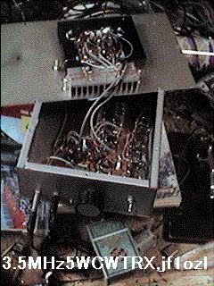 35mcwph.gif
Four side of upper cover are cut for the heat hole.
Sorry but please read the last page before read this page !
The reason of QRV
I operated 3.5MHz SSB for two weeks. But 10W SSB was too weak to make CQ
by myself. I could operate to wait for somebody's CQ. 3.5MHz band is very
noisy in Japan. Therefore I decided to make and operate 3.5MHz CW with
QRP.
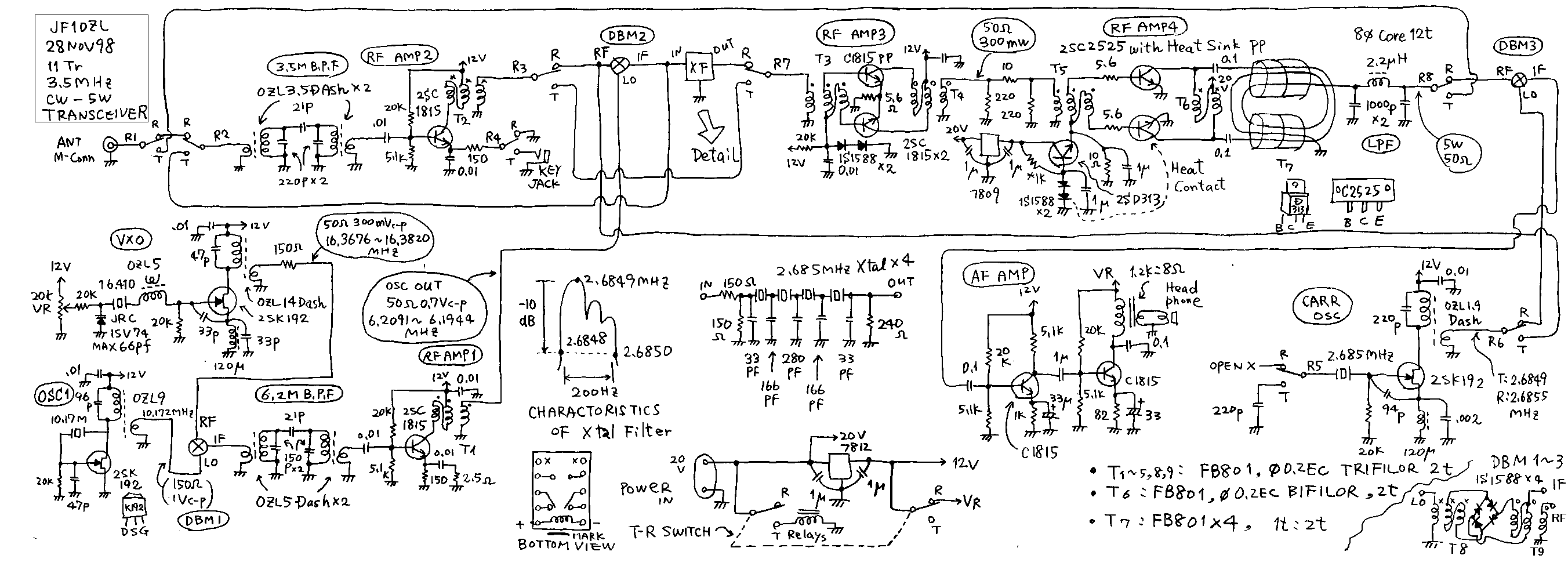
Circuits and typical point
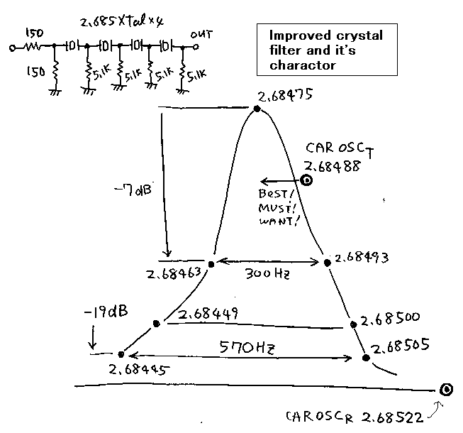
1. I have 500 of crystals on my shack. In order to make crystal filter
for CW operation I used 2.685 MHz named crystals. In order to make narrow
pass band filter , it is good to use the crystal lower than 4MHz. In order
to make SSB filter , it is good to use the 9 or 11 MHz named crystals.
On the first time I made the crystal filter indicated on the center of
the hole circuit diagram. The band width of it was 200Hz. The shape of
it was very good. But when I used this transceiver , I knew that such a
too narrow filter was not so good for the real operation. Somebody answered
my CQ 100Hz lower of my sending frequency. Then I could not hear his signal.
Then I watched the band, I could hear two station operates another frequency
about 100Hz each other. Therefore I improved the filter. The band width
of it was made as 300Hz. The character of it becomes the shape like a Fuji
Mountain. Fuji mountain is a beautiful and highest mountain in Japan.
2. Also in this gear, I used the common circuit method of transmitter and
receiver. With only 12 transistors, I could make useful transceiver. But
I need many relays to change circuits.
3. See the circuit diagram ! You can see some coils named OZL dash. OZL
series coils are the imitation of FCZ coils. OZL dash series are the improvement
of them. In order to make more high Q coils, I winded second winding of
OZL coils half of original. It is OZL dash series.
4. The case has many holes on the side wall of it. It is junk case.
5. Action of receiver
5-1.The 3.5MHz CW signal pass through 3.5MHz band pass filter. And it is
amplified by AMP2.
5-2.This signal is injected on the RF port of the DBM2 , converter.
5-3.On the another hand, OSC1 oscillator makes 10.172MHz signal.
5-4.On the another hand, VXO oscillates the signal from 16.3676 to 16.3820MHz.
5-5.The signal from OSC1 and VXO is mixed on DBM1 mixer and the difference
of them is coming on the IF port of the DBM1 mixer. The frequency of it
becomes from 6.1956 to 6.210MHz. A local oscillator made by mixing two
another oscillators is called as pre-mix oscillator.
5-6.By introducing this pre-mix oscillator on the LO port of the DBM2 converter
,I can get the 2.68475MHz IF signal , as the difference of the LO and RF
port of the DBM2.
5-7.This IF signal pass through the crystal filter, and amplified by the
AMP3 and AMP4.
5-8.This IF signal passes through the low pass filter, and injected on
the RF port of the DBM3, demodulator.
5-9.On the other hand, CARR-OSC(This name is depend on that this oscillator
works as a carrier of SSB demodulator .But in this case it may be not proper
name. It may be better to call it as BFO; beet frequency oscillator) makes
the 2.6855MHz signal. And it is injected on the LO port of the DBM3, de
modulator.
5-10.Therefore the 750Hz audio signal occurs on the IF port of the DBM3
demodulator as the difference of "2.6855MHz LO signal" and "2.68475
IF signals on the RF port".
5-11.This audio signal is heard by head phone after amplified by the two
stage audio amplifier.
6.Block diagram of receiver
| ANT |
3.5M
BPF--> |
AMP2
----> |
DBM2--->
convertor |
2.68MHz
X.filt--> |
AMP3
--> |
AMP4
--> |
LPF
--> |
DBM3--->
demodulator |
AF,AMP
---> |
AF,AMP
---> |
Phone |
|
|
|
go upside |
|
|
|
|
go upside |
|
|
|
| VXO |
---+
........l |
|
go upside |
|
|
|
CAR
OSC |
go upside |
|
|
|
|
DBM1--> |
6.2M
BPF |
AMP1
go upside |
|
|
|
|
|
|
|
|
| OSC1 |
........l
---+ |
|
|
|
|
|
|
|
|
|
|
7.Put the relation of each frequency of circuits of the receiver in order
!
Fvxo: Frequency of VXO: from 16.3676 to 16.3820MHz
Fosc: Frequency of OSC1: 10.172MHz
Flo: Frequency of output of local oscillator: Flo=Fvxo-Fosc1
Fif: Frequency of IF = Center frequency of crystal filter=2.68475MHz
Fr: Frequency of received signal: Fr = Flo-Fif =(Fvxo-Fosc1)-Fif = Fvxo-(
Fosc1+Fif)=Fvxo-12.8567=from 3.5109 to 3.5253MHz
In Japan 3.5MHz CW band is from 3.5000 to 3.525.
This rig covers about 60% of this band.
Holding the bug full of chrystal on the knee,taking culculator on the left
hanmd, taking ball pointed pen on the right hand, I make frequency plann
of this transceiver about five hours. It was most enjoynable time. It is
similor as making travel plan with train scadule book.
8. Signal flow of the transmitter
8-1.On the transmitter ,the premix local oscillator works same as the receiver.and
the output of this oscillator is injected on the LO port of the DBM2 mixer.
8-2.On the other hand OSC2 makes signal of 2.6849MHz. On the transmitting
time, the 220pf capacitor is connected on the crystal of the OSC2, therefore
the oscillated frequency becomes somewhat lower than the receiving time.
8-3.DBM mixes the two signal. And DBM occurs the 3.5MHz signal on it*s
IF port.
8-4.This 3.5MHz signal passes through the 3.5MHz band pass filter. And
it is amplified by the AMP2,AMP3 and AMP4 RF amplifiers.
8-5.This 5W signal is purified by the low pass filter. The coil of this
low pass filter is made by winding 0.2mm diameter enamel wire around 8
mm diameter core bobbin for 14 turns.
8-6.I have forgotten to explain about the key. The emitter of the transistor
of AMP2 is controlled by the key only on the transmitting time.
9.Block diagram of transmitter
CAR
OSC |
---+
........l |
|
|
|
|
|
|
|
DBM2--> |
3.5M
BPF---> |
AMP2--> |
AMP3--> |
AMP4--> |
LPF--> |
ANT |
primix
OSC |
........l
---+ |
|
Key
on emitter
of AMP2 |
|
|
|
|
10. Put the relation of the frequency of the transmitter in order!
Flo:Flo is same as receiver.
Fcar: Frequency of CAROAC=2.6849MHz
Ft: Frequency of transmitting signal : Ft=Flo-Fcar=Fvxo-Fosc-Fcar=Fvxo-(Fosc+Fcar)
=Fvxo-12.8659= from 3.5107 to 3.5251
11. Data of 2SC2525
2sc2525:Maker=Fujitu:Power amplifier:construction=Silicon EP:Vcbomax=120V:Icmax=12A:Pc=120W:Hfe=110:ft=80MHz
The ft of it is only 80MHz. This transistor is made to use on the power
transistor of an audio amplifier about 50W class. But it can be used on
the lower frequency of HF.
12.Log with this transceiver
| data |
Japanese time |
QSO with |
RST I send |
RST I got |
His location |
distance from my shack(km) |
| 30Nov98 |
2303 |
JI1GQO |
599 |
569 |
Higashimatsuyama-city |
75 |
| " |
2340 |
7M3ROM |
599 |
449 |
Machidas-city |
87 |
| 1Dec98 |
2320 |
JH1NRT |
599 |
599 |
Minato-ku |
60 |
| 2Dec98 |
2052 |
JA8BOL/7 |
599 |
379QSB |
Oofunat-city |
360 |
| " |
2222 |
JH1RZY |
599 |
559 |
Funabashi-city |
42 |
| " |
2302 |
JO1LJG |
599 |
599 |
Aso-gun |
30 |
| " |
2355 |
JJ2LNA |
599 |
599 |
Fujinomiya-city |
170 |
| 3Dec98 |
2327 |
JE3HHT |
599 |
589 |
Takatsuki-city |
400 |
| " |
2357 |
JI0JLC |
559 |
319 |
Minamiuonuma-gun |
160 |
| 4Dec98 |
2122 |
JH1LVB |
559 |
579 |
Kawasaki-city |
75 |
| " |
2148 |
JN6BNB |
559 |
559QSB |
Mii-gun |
940 |
| " |
2235 |
JL3VJT |
579 |
589 |
Kyoto-city |
420 |
| " |
2302 |
JA0PX |
559 |
559 |
Niigata-city |
200 |
ADD:22MAR99:
I made over sea QSO with this gear. DS4BXZ. 22mar99,2120JST, RST599send,
559receiv.
3.5mcw.gif
3.5mcwfil.gif
3.5mant.gif:view of my 3.5MHz antenna. 我が家の3.5MHzアンテナの様子
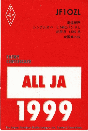
Discription add on 3 Jun2000:35cwallja.gif
I got with this rig a contest award, all ja 1999 single operater 3.5MHz
CW , No6 in Japan.
lower from here Japanese
3.5MHz12石式5WCWトランシーバー:3.5mcwph.gif
 35mcwpf.gif

上蓋(ふた)の四隅は、風穴の為にきり欠いてある。
すいません、このページを読む前に、前のページの3.5MHzSSBをお読みください。続編になっております。
QRVした理由
3.5MHzのSSBを2週間運用してみて、以下の事を感じました。ひとつには、3.5MSSBで10Wではやはり今時つらいです。お相手して下さる局も在るんですが、何しろ、ノイズとの戦いで、39QRNなんてレポートをもらいます。つまり信号はそこそこに来ているのですが、ノイズが多くて了解度が悪いっていう事です。このバンドでは500Wなんていうのが「ベアフットに毛の生えた出力」と称されています。この狭い日本でも、見渡す限り自分の畑とか山で、そのほんの片隅にフルサイズ40メーターの長さのダイポールを上げて、キロワットをなんの躊躇(チュウチョ)も無く出していらっしゃるOMが、多数いるんですね。そういう局長さんがメインのバンドなのです。逆に50MHzは都会のバンドで、51なんてレポートが、普通です。つまり、Sメーターは振れなくても、ちゃんと了解出来るって意味です。まあ、そういった訳で、3.5Mでは10Wは超QRPで、日常の運用はちょっとつらい。CQを出してる局が近くにいて、たまたま誰も応答しなかった時にでくわせて、たまたまその局長さんが、ヘッドホンを付けていてノイズの中から弱い信号を取ってくれる根性が有
った場合のみ、コンタクト出来るといった具居合いです。いくらCQをだしても全然応答はありませんでした。そこで、CWならもっとましに、運用できるのではと思って、この機械を作ってみました。結果はほどほどといった所でしょう。こちらからの、CQにも応答してもらえました。但し、私は、10年間、7MHzのCWを運用してきましたので、お会いする局の「さんぶんのに」は、7MHzでお相手いただいた局です。これが唯一の不満ですが、致し方ないという物でしょう。ちなみに、私は和文が出来ません。もし、和文が打てれば、交信局数は2〜3倍に増えたでしょう。(仮定法過去:もしもあのひあなたにあわなければ、tuturutututu-)
回路構成
1.CW専用のトランシーバーとなれば、クリスタルフィルターは200Hzか300Hzの狭帯域の物を作って、SN比の向上と、バンドを有効に使う事を心掛けねばなるまいて。そこで、狭帯域のCW専用フィルターを作るためには、4MHzか2MHz代の低い周波数うの水晶が最適であるという事はわかっている。ごそごそと、5キログラムほどある、水晶の買い溜め袋をあさると、2.685MHzの名版周波数の水晶が5個あった。これだ!適当にコンデンサーをつないで、ラダーフィルターを組んでみると、200Hz帯域のものができた。OK!7MHzで300Hz帯域の物を4年ほど使っているがFBであるから、200HzはもっとFBに違いない。
しかし、ばっと、結論を申し上げると、これは間違いでした。200Hzの帯域は狭すぎて、2局が交信しているのに、片方しか聞こえなかったり、自分のCQに応答してくれた局が帯域外で、聞こえなかったり、電源投入から1時間位間のQRH(周波数変位)に対応できなかったりで、使いにくい物でした。そこで、今は、図2の、300Hz富士山型フィルターに変えて、すこし「切れ」を甘くして使っています。これで、納得。
2.今回の製作でも「送受信共用」による回路の簡素化と、リレーの多用は,前に作ったSSBのリグと同じコンセプトです。OZL方式と呼んでください!
3.回路図にいくつか「OZLダッシュ」なる新しいコイルの記号がご覧になれるでしょう。FCZコイルは、1次の同調側の巻き数のだいたい「さんぶんのいち」が2次側の巻き数になっています。これでは、たーとーえーば、例えば、例えば、例えば、2次側の、すなわち負荷側のインピーダンスが50オームの場合に、1次側のインピーダンスは、50かける3の2乗で、たった450オームなのです。これでは、このコイルをフィルターに使ってもQが低いですし、発振回路のタンク回路に使った場合には、負荷の影響が発振回路の動作に強く影響を与えてしまって、動作が安定しません。そこで、対策として、FCZシリーズの2次巻き線の巻き数を半分にした、「改造FCZシリーズコイル」を、「OZLダッシュ」なる新しいコイルの記号としました。大久保OM。すいません。
4.箱には、先日催された「ラーバンフェスタ」でもらって来た、どちら様かのジャンクのケースを使っています。アイデアルのP1のケースで、Mコネ用らしき風穴(かざあな)が横にたくさんあいますが、通風の為と思っています。
5.受信時の信号の流れ。
5−1.アンテナから入ってきた、3.5MHzの信号は、バンドパスフィルターを通ったあと、AMP2で増幅されます。なんで、いきなりAMP2なのかって。いいでしょう。そのクラスの一番前にすわっている少年は「次郎」さんなんです。HI。
5−2.この信号が,周波数変換機のDBM2のRFポートに、はいります。
5−3.一方、OSC1では、10.17MHzの水晶発振器が働いています。
5−4.また、一方、VXOでは、16.41MHzの水晶をつかって、周波数可変水晶発振器がくまれており、16.3676から、16.3820MHzが発振されます。
5−5.さきほどの、VXOの信号とOSC1の信号がDBM1で混ぜ合わされて、その差の周波数である6.2091から6.1944MHzの信号が取り出されます。これが、RFAMP1で増幅されて、5mWの局発信号になります。この様に、あらかじめ2個の発振器の信号をまぜあわせて、1つの局発信号として使う方式を「ぷりみくす方式」(「あらかじめ混ぜる」という意味)といいます。
5−6.この局発信号を5ー2.項のDBM2の周波数変換機のLOポートに入力しますと、DBMの出力であるIFポートには、LOポートとRFポートの信号の差として、2.68475MHzの信号が出てきます。
5−7.この信号は、水晶フィルターの中を通ったあと、その後の、中間周波増幅器として、AMP3とAMP4で増幅されます。
5−8.この中間周波信号はローパスフィルターをぬけて、復調器DBM3のRFポートにはいります。
5−9.一方、CARRーOSCでは、2.6855MHzの信号が発振されており、これがDBM3のLOポートに入力されています。この時水晶は、切り替え回路の、同軸ケーブルの容量だけで、接地されています。
5−10.よって、DBM3では2.68475と2.6855MHzの差である、750Hzのポーという音になって、CW信号が音声化されます。
5−11.この音声信号は、AFAMP(音声信号増幅器)で2段増幅され、ヘッドホンできかれます。「聞かれます」という日本語はおかしいかな。聞こえますかな。聞けますかな。だいたい「信号」を主語にした時点で、すでに間違いかも。
6.受信時ブロックダイアグラム
| ANT |
3.5M
BPF--> |
AMP2
----> |
DBM3--->
convertor |
2.68MHz
X.filt--> |
AMP3
--> |
AMP4
--> |
LPF
--> |
DBM3--->
demodulator |
AF,AMP
---> |
AF,AMP
---> |
Phone |
|
|
|
go upside |
|
|
|
|
go upside |
|
|
|
| VXO |
---+
........l |
|
go upside |
|
|
|
CAR
OSC |
go upside |
|
|
|
|
DBM1--> |
6.2M
BPF |
AMP1
go upside |
|
|
|
|
|
|
|
|
| OSC1 |
........l
---+ |
|
|
|
|
|
|
|
|
|
|
7.受信時の周波数関係の整理
Fvxo:VXOの発振周波数:16.3676から16.3820MHz
Fosc1:OSC1の発振周波数:10.172MHz
FLO:局発の出力:FLO=FvxoーFosc
Fif:水晶フィルターの通過帯域中心周波数:2.68475MHz
Fr:受信周波数:Fr=FLO−Fif=FvxoーFoscーFif=Fvxo−(Fosc+Fif)=Fvxo−12.8567=3.5109から3.5253
3.5MHzのCWバンドは3.500から3.525MHzなので、大体60%をカバーしている。
周波数の計画をするのが、トランシーバーの製作のなかで、最も楽しい時間です。それは、時刻表を片手に、旅行の計画を立てるのに似ています。いったん、製作が始まってしまえば、後は力仕事ですから。
500個の水晶をもっていますが、フィルターが組める同じ周波数の物は10種類くらいです。だから、それを最初に決めて、局発周波数をどうにかして、つじつま合わせをする、という手順になります。たとえばその局発が6.21MHzが必要だとなったとして、いくら500個の水晶があっても、ぴったりの物があるとは限りません。そんな時、今回のプリミクス方式が役に立ちます。任意の500個の水晶の内の2個の差の周波数の組み合わせは、500の階乗、つまり電卓で答えが出ない位おおきな数です。すなわち、プリミクスによれば、たいていの周波数はできてしまうという事です。
8.送信時の信号の流れ
8−1.プリミクス方式の局部発振器は、受信時と全く同じに動作している。この、信号はDBM2のLOポートに入っている。
8−2.一方、CAR、OSCすなわち、2.685MHzの水晶発振器は、送信時には水晶に220pfが直列につなげられるので、発振周波数がちょっと低くなって、2.6849MHzになります。
8−3.このCAR,OSC信号がDBMのRFポートにはいるので、そこで混合されて、差の3.5MHz周波数がでてきます。
8−4.この3.5MHzの信号は、3.5MHzのBPF(バンドパスフィルター)を通ったあと、AMP2、AMP3、AMP4でどんどん増幅されて、5Wの信号になります。
8−5.5Wの信号はπ型1段のローパスフィルターを通ったあと、アンテナから放射されます。
8−6.言いそびれましたが、AMP2のトランジスタは、送信時にはキーで断続されるので、CW信号が断続されます。
9.送信時のブロックダイアグラム
CAR
OSC |
---+
........l |
|
|
|
|
|
|
|
DBM2--> |
3.5M
BPF---> |
AMP2--> |
AMP3--> |
AMP4--> |
LPF--> |
ANT |
primix
OSC |
........l
---+ |
|
Key
on emitter
of AMP2 |
|
|
|
|
10.送信時の周波数関係の整理
10−1.FLO:受信時と同じ
10−2.Fcar:CAR,OSCの発振周波数:2.6849MHz
10−3.Ft:送信周波数:Ft=Flo−Fcar=FvxoーFosc−Fcar=Fvxoー(Fosc+Fcar)
=Fvxo−12.8569=3.5107から3.5251MHz
11.2SC2525の規格
2sc2525:Maker=Fujitu:Power amplifier:construction=Silicon EP:Vcbomax=120V:Icmax=12A:Pc=120W:Hfe=110:ft=80MHz
ま、つまり、オーディオの出力用のトランジスターです。ステレオの出力段に使って、50W位だすための石でしょう。HFの低い方なら十分使えます。100円です。
12.運用結果:毎日仕事から返って、1時間位運用して、呼んだ局、呼ばれた局あって、1日2ー3局でした。運用結果はまずまずでしょう。但し、平日の夜は、バンド内に2ー3局しかでて居ません。がらがらです。土日でも5ー6局でしょう。すいてます。出てきてください。
| DATE |
日本時間 |
交信相手 |
送ったRST |
もらったRST |
相手の住所 |
家(土浦)からの距離km |
| 30Nov98 |
2303 |
JI1GQO |
599 |
569 |
東松山市 |
75 |
| " |
2340 |
7M3ROM |
599 |
449 |
町田市 |
87 |
| 1Dec98 |
2320 |
JH1NRT |
599 |
599 |
港区 |
60 |
| 2Dec98 |
2052 |
JA8BOL/7 |
599 |
379QSB |
大船渡市 |
360 |
| " |
2222 |
JH1RZY |
599 |
559 |
船橋市 |
42 |
| " |
2302 |
JO1LJG |
599 |
599 |
麻生郡 |
30 |
| " |
2355 |
JJ2LNA |
599 |
599 |
富士宮市 |
170 |
| 3Dec98 |
2327 |
JE3HHT |
599 |
589 |
高槻市 |
400 |
| " |
2357 |
JI0JLC |
559 |
319 |
南魚沼郡 |
160 |
| 4Dec98 |
2122 |
JH1LVB |
559 |
579 |
川崎市 |
75 |
| " |
2148 |
JN6BNB |
559 |
559QSB |
三井郡 |
940 |
| " |
2235 |
JL3VJT |
579 |
589 |
京都市左京区 |
420 |
| " |
2302 |
JA0PX |
559 |
559 |
新潟市 |
200 |
追記:22MAR99:先ほど、22MAR99、2120JST,韓国DS4BXZ局と交信しました。このTRXで初めての海外交信です。といっても、韓国は南九州よりも近いけど。RST599送り、559をちょうだいしました。TNX:PARKOM。
追記:3JUN2000。35cwallja.gif
ここで、紹介したRIGを使用して、下記のコンテスト入賞賞を取得した事をここに発表いたします。1999、ALLJA、3.5MHzCWシングルオペ部門全国6位、でした。このリグと、別のページに紹介してある「テープレコーダ式オートQCマシン」を使っ2日間CQを出しまくった成果です。

back to index
 35mcwph.gif


