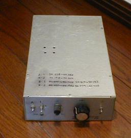
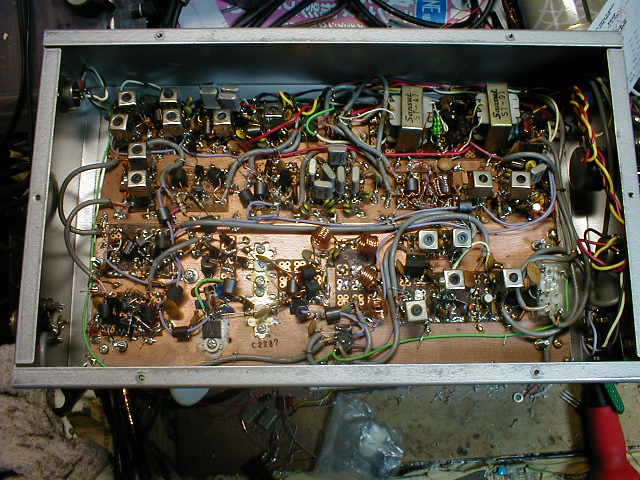
2.My 50MHz 2W SSB rig
The following schematic is of my favourite transceiver because it was made
by hand by myself. The rig was completed on the 25th of February, 1996,
and in the following year, I made about a thousand QSO's on it. This rig
was built for use both at home and while sitting in my car on top of a
local hill. To operate from the car, I set up two elements of an HB9CV
antenna. Twelve volts d.c. is supplied from the car through the cigarette
lighter socket and so this rig does not require an internal supply. I will
explain the function of each of the sections of the circuitry one by one
starting with the transmitter. I use a 600 Ohm dynamic microphone. The
audio signal from this microphone is amplified by an audio power amplifier,
the classical push pull amplifier circuit using input and output transformers.
On the primary of the output transformer, an l.e.d. limiter is used. This
limiter restricts the signal on the secondary, the modulating signal, to
less than 1 Vc-p. This limiter drops the peak voltage of a voice signal
by about 50%. The carrier oscillator and buffer amplifier make a carrier
at a level of 3Vc-p. With this combination, the modulating signal is about
10dB lower than the carrier level. To create a good double side band signal,
modulation must be limited to this extent below the carrier signal. For
a modulator, I use a ring diode circuit. It is made from two ferrite cores
(FB801, trifilar) and four germanium diodes (1N60). This type of modulator
can be used bilaterally so that it can be used for demodulation on receive.
I tested and selected many pairs of diodes in order to make the signal
linear. I experimented with two diodes in parallel but now use just one
diode. You must check the linearity of the modulated signal at the i.f.
port of the modulator using an oscilloscope.. The crystal filter changes
the double side band signal to a single side band signal. The crystal filter
is fabricated by using six C.B. crystals. Because of impedance mismatch,
other operators said that the quality of my voice was hard". To correct
this distortion, I used a 200 Ohm resistor at the front end of the filter
and thereby reduced the ripple of the filter. (((Not only ripple but also
to reduce missmatch of the impedance thgis shunt resister works.)))****
This filter passes the frequencies between 10.6155 and 10.6187 MHz. The
carrier frequency is 10.6187 MHz. I employ the same junk 10.615 MHz crystals
both in the oscillator and filter. At the f.e.t., by putting a crystal
between the drain and the gate, you can make a carrier at the top end of
the filter pass band. The oscillator frequency must be tuned by a capacitor
(in this particular case, 56 picofarads and 22 picofarads in parallel)
in order to set the oscillation at the top end of the filte's pass band.
I tested many types of oscillator but I could only make lower side band
with these six junk crystals for the filter plus one for the vxo carrier
oscillator. So what I ended up doing was creating a lower sideband signal
first and then creating and upper sideband signal by inverting the phase
in the following converter stage.
***memo:upper discription was rewritten by John VE7AOV. Downside is original
poor English by Kaz Sunamura.HIHI.Thanks John.1 Feb 2000**
To change phase by the converter (In this
case “phase converter “is not correct word. But I like this word, because this
word is used on the star trek... To say more frankly, I do not know correct
word. HIHI), transmitting signal must be made by minus calculation from IF
signal and local signal. So I must make 60MHz local signal.
60MHzCW-10MHzLSB=50MHzUSB.
If local signal was 40MHzCW, 40MHzCW+10MHzLSB=50MHzLSB, I will not be able to
make QSO with any station, because 50MHz SSB must be operated by USB.
To make local signal, I selected circuit. 10MHz VXO can be make very stabilized
CW signal and it can be tuned by Varicap-diode about 3KHz, and it is multiplied
6 times by *3 and *2 multiplier. Generally speaking, VXO can be changed its
frequency about 0.5% of oscillating frequency. But in this Rig, it is tuned
only 3 kHz and 3 KHz/10MHz is only 0.03%. It is easy way to make stabilized VXO
oscillator that to make it with small tune -ability. One crystal can make about
20kHz tune-ability in 50 MHz. And I use small relay to change two crystals (10.14
and 10.16 MHz). This rig does not cover 50MHz full band. You can learn about
push push Tripler and push pull doubler on the ARRL handbook. I like this type
of multiplier because it can products required signal stronger than another
unrequired signals. You can see the name of coil in the schematics as
"OZL28" and "OZL50". These are similar coils from FCZ28 and
FCZ50 sold in Japan for use of Amateur radio builder. But OZL series coils are not sold
in Japan and only made and used by myself. I break some junk coils and
rewire them by same turns as FCZ series, I name them OZL series.hihi.
The converter is made by wide band active mixer. This circuit is like as push
pull amp, but input and output coils are made by trifiler wide band
transformer. Diode mixer has about 10dB signal loss, and it works safety. Tuned
active mixer has about 20dB gain, but it sometime oscillate by itself and makes
unwanted signal. Wideband passive mixer has no gain and no loss, and it works
stable. So I like this type of mixer.
Mixer makes not only 50MHz USB signal but also 70MHz LSB signals. So you must
stay 50MHz band pass filter after the mixer. And after the mixer, power AMP is
located to make 50MHz signal from 0.5Vc-p to 15Vc-p (=2 watts). Power amp is
constructed by wide band amplifiers. I will not describe about it, because it
is written in many books. But I say you that to avoid the self oscillation, you
must care about some points. Try and error the attenuator between first and
second amp! Try and error the input resister on the base of transistor (10
ohm)! Try and error the emitter resister (5 ohm of 2SC1815)!
At the end of power amp, the low pass filter is located. It is need to avoid
The TVI. Coil is made by 1.0 mm diameter enamel coated wire, and it is formed
around "RED" pencil for 6 turns.
I will explain about receiving time. Signal coming from antenna is through the
50MHz band pass filter and it is amplified by FET (2SK241) RF AMP. In this
transceiver receiving converter is made by two gates FET (3SK59). This pair of
front-end circuit is very popular as standard for amateur radio builder in Japan. I
have no doubt that it work safety and have enough gain. To make DX QSO, you can
challenge two stage RF amplifiers, but it sometimes makes self oscillation and
it sometimes make inter modulation QRM.
IF amplifier is commonly used as transmit and receive. The flow of signal is
changed by relays. We can use small relays like TQ2-12V made by National Company
to change the RF signals. And modulator of transmitter acts as demodulator on
its receiving times, and microphone amp is used as audio amp in its receiving
times. But as receiver, only one stage amp does not have enough gain, so AF
preamp is used only in its receiving time. And the normal variable resister is
used to adjust the volume of audio signals.
My rig has no S-meter and no automatic gain control. Because it has no
automatic gain control, I can understand the strength of received signals by my
ear. And so I can make signal report by my ear. We call that "Ear-S" in
Japan.
This RIG uses two oscillators on the time of transmit and receive commonly, so
I am not afraid that the carrier frequency is changed between transmit and
receive. So I feel no need for Rit system. I sometime say to my QSO friend that
his rig changes frequency between transmit and receive timing.
This Rig is not build for DX QSO. But I can make many QSOs with Tokyo and Yokohama stations
setting this Rig on the hill near from my hometown located a part of Tsukuba Mountain in Ibaraki prefecture.
At the end of this page, I will show you the character of the transistors.
2SC1815: Maker= Toshiba: usage Low frequency amplifier general use: Vcbo=60V:
IcMAX=150mA: PcMAX=400mW: hfe=70 to700: fT=80MHz
2SC3510: Maker= Hitachi: usage UHF ,VHF amplifier: Vcbo=20V: IcMAX=50mA:
PcMAX=600mW: hfe=30 to200: fT=3500MHz: Typical 10.5dB on 900MHz
2SC2287: Maker= NEC: usage VHF power amplifier: Vcbo=38V: IcMAX=1.5A: PcMAX=17W:
hfe=20 to200: Typical 38.5dB on 175MHz Power in 26dBm
2SK241: Maker= Toshiba: usage= FM VHF Radio frequency amplifier: Mos N
channel: VMAX=20V: Idss=10mA: gm=10mSmax: Cis=3pF: Crs=0.035pF: Power gain
28dB typical on 100MHz
3SK59: Maker= Toshiba: usage= VHF Radio frequency mixer: Mos : VMAX=20V:
Idss=10mA: gm=20mS typical: Cis=5pF: Crs=0.03pF: Power gain 24dB typical
on 100MHz
下の図は、私が今一番使っているリグです。1996年の2月に作り約1年で1000局とQSOをしました。このリグは家で使ったり、あるいは車で近所の峠へいって使うために作ったもので、電源は車のシガライターや家の直流安定化電源からもらうので、特に電源装置を内臓していません。
この回路は、1992年の4月号のCQ誌に掲載された私の作品「6石式SSBTRX」の発展版です。バックナンバーをご覧になれる方はあわせてご覧ください。(杉並図書館へ行けば全てのバックナンバーが読めます。)
まず、送信時の各回路の働きを説明します。私は、600オームのダイナミックマイクを普段使っています。その信号はまず、トランス入出力タイプの昔ながらの形のプッシュプルオーディオアンプで増幅されます。この出力トランスの1次側にはLEDによるリミッター(振幅制限器)が付いていて、変調信号であるオーディオ出力信号を1Vc−p(センターツーピーク)に押さえます。私が大きな声でしゃべると、ピーク波形の上側約50%が削り取られます。一方、搬送波発信器(キャリアーオッシレーター)の信号強度は3Vc−pですから、搬送波は変調波よりも10dBほど小さい事になっています。最初作った時は、ダーオードを3個直列に使っていたので、もう少し変調信号が強くて、そのかわりピークで歪んでしまい、QSOした「各局」からクレームを頂きました。それで2個直列にして見ました。これでオッケー。(((アマチュア無線家の中には「カッキョク」という表現を、極端に嫌うOMもいますが、私はCB上がりですので。de
ex杉並1553)))
変調には、リングダイオード式の平衡変調器を使っています。これは1N60というゲルマニウムダイオード4個と、FB801というフェライトビーズを2個使って自分で作った物です。トランシーバーとして使いはじめてから各局に音が悪いと言われ、いろいろこの変調器の直線性を改善するためにダイオードを並列にしてみたり、選別したりして今日に至っています。皆さんも作られたら、IFポートにオッシロスコープをあててチェックしてください。ここで作られた両側帯波抑圧搬送波(DSB;Double
sideband signal)が、次のフィルターで片側の側帯波を削り取られていよいよ片側帯波抑圧搬送波(SSB;Single
Side Band)になります。クリスタルフィルタはジャンクのCB用水晶6個をラダー型に組み構成しています。最初、やはり音が硬いとレポートされたので、入力に200オームの抵抗を追加して、インピーダンスマッチングをとって、特性を改善しました。(((すなわち、シャント抵抗無しでは、クリスタルフィルターは周波数の変化で入力インピーダンスが50オームから数百オーム程度まで変化しますが、ダイオード変調機の出力インピーダンスは50オームで一定なので、結果的に低域内外で伝達利得が暴れるわけです。)))帯域特性の大体の様子が回路図に描いてあります。このフィルターの通過帯域は10.6155MHzから10.6187MHzとなりました。そこでキャリアーの周波数を10.6187MHzに持ってきて、SSBそれもLSB(Lower
sideban)信号にします。フィルターも搬送波発信器も同じ10.615MHzの名版周波数の水晶で作るのです。回路を指定して、水晶屋さんに注文して、指定の周波数で作ってもらう様なわけにはいかず、何とか手持ちの部品で、通過帯域のはしっこに発信周波数を持って来なくてはSSB信号ができません。ラダーフィルターを作ったのと同じ水晶を使い、電界効果トランジスターのドレインとゲートの間に水晶を入れて作った発振器で、ラダーフィルターの上端の周波数が発信できます。最終的には搬送波発信器のゲートとグランドの間のコンデンサー(56Pと22p)やドレーンにつないであるコイル等で周波数を調節します。(逆の話ですが、皆さん一度は水晶を注文して作って見ましょう。駅前のすし屋さんに、電話で「特上!!!!」を頼むのと同じ感覚でできます。)中間周波増幅器は2SC1815の広帯域増幅器です。ゲインは約25dBあり、送信時のレベルの調整(次の周波数変換機の入力電圧として適当な電圧になる様に増幅)を行っています。さて、ここで10MHzのLSBができましたので、これを50MHzのSSBそれもUSBにしなくてはいけません。そこで、60Mの信号か
ら10MのLSBを引き算して50MHzのUSBを作ります。60MHzCW−10MHzLSB=50MHzUSBと成ります。もし代わりに40MHzのCWを持ってくると、確かに50MHzのSSBはできるのですが、USBではなくてLSBに為ってしまい、交信相手がいなくなってしまいます。すなはち、40MHzCW+10MHzLSB=50MHzLSBとなります。この計算式で、LSB信号の所のプラマイ記号が、プラスならLSBのまま、マイナスならUSBに変化します。局部発信器(ローカルオッシレータの直訳でおかしい言葉ですね!話が違いますが貴方はimmunityを何と訳しますか?「感受性?」やめてください!15の女の子じゃあるまいし。「イミュニティー」でいいでしょ。)には、10MHzの水晶を使ったVXOを使用し、これを6逓倍しています。VXOは普通、発信周波数の0.5%程度周波数が動かせるものですが、ここでは10MHZの発信周波数に対してたった3KHz、つまり0.03%しか動かしていません。そのため、送信周波数は大変に安定で、QRHをリポートされた事はありません。次の10MHzを30MHzに3逓倍するプッシュプッシュトリプラ
ー(押し押し3逓倍器)はちょっと変わった回路です。詳しくはARRLのハンドブックに説明してあります。次のプッシュプルダブラーと合わせて、私は大変このタイプの能動逓倍器が好きです。とにかく出力最大にコアを調節すれば間違った周波数が出てくる心配がありません。逓倍器とミキサーの間には広帯域増幅器が緩衝増幅器としていれてあります。周波数を変換するのが次の混合器(ミキサー)です。この回路は図面を見て頂くと分かる様に、局部発信器の後の緩衝増幅器と酷似した回路で、ただエミッターの所に局発信号を入れたところが違うだけです。ダイオードミキサーは安定して動作するのは良いのですが、10dB程度のロスがあり、結果として同じ出力を送信する為には、10dB分だけ、次の直線増幅器(リニアーアンプ)の増幅率に負担がかかってしまいます。また、同調式の周波数変換器は25dB程度の利得が期待できますが、自己発信の危険と背中合わせの回路です。そういったわけで、私はこの広帯域能動型の混合器が気に入っています。局発用水晶は1個あたり、たった20kHzしか広い((な。なんと4メガもある))50メガバンドの中でカバーしてくれませんから
、小さなリレーで水晶を切り替えて使用しています。ナショナルのTQ2ー12Vとゆうリレーを使っています。混合器は50MHzUSBの他に70MHzのLSBや60MHzの局発信号の通り抜け等も含んでいるので、混合器と直線増幅器の間には、帯域瀘波器(たいいきろはき:バンドパスフィルター)をいれてやります。その後の直線増幅器は普通の広帯域増幅器です。あまり変わった所はありませんが、注意点を述べます。2段の増幅器の間のアッテネーター(日本語を知りません、減衰器かな?)は、増幅器が発振しないでしかも適当な総合利得が得られる様に、調節(カットアンドトライ)してください。1段目の増幅器のトランジスターのエミッターの所の帰還抵抗5オームも調整点です。2段目のトランジスターのベースの10オームも調整点です。本に書いてある回路をそのまま組んでもなかなかうまく動かないもので、妥協しながら調整する必要があると考えてください。最後にアンテナとの間にはローパスフィルターが入れてあります。これはTVI対策として必要です。コイルは赤鉛筆の周りに1.0
mmの径のエナメル線を6回巻いたものです。これを4個使います。
次に、受信時の回路を説明します。2SK241の高周波増幅器とデュアルゲートFET(3SK59)のミキサーコンバーターは、いわゆる定番とゆう物です。DX向けには、高周波増幅を2段にして利得を稼ぎますが、これはいわゆる内部混変調(((用語として正しく無いのは承知です。しかしすでに「市民権」を得ています。同様に「全く」という言葉が否定語と共にでなく使用されるのにも私は賛同します。)))を発生し、コンテストの時にバンドじゅうがバサバサいって使い物にならなくなってしまうので、お勧めしません。受信時の中間周波増幅は送信用の中間周波増幅器をリレーで切り替えて使っています。受信用にはもう20dBほど利得を稼いでおきたい所ですが、私には不足はありません。復調器(デモジュレータ)も送信用の変調器を共用しています。リレーの数が増えるのを嫌う方もいますが、送信時と受信時で搬送波発信器の負荷が変わらない事は周波数の安定に一役かっています。低周波増幅も送信用の増幅器と共用ですが、利得を得る為に、受信時だけ前置増幅器(プリアンプ)を1段入れています。一応ボリュームを入れて、ローカル局との交信時には絞れる様に為ってい
ます。私には、いわゆるスーパーローカルが居ませんので、この前で信号が飽和する心配はありません。ですから、この前に利得調整回路は必要ありません。この機械にはSメーターがなく、いわゆる(多くてすいません)耳Sを送ります。自動利得調節(オートマッチクゲインコントロール)も無い為に、耳Sでも結構正確に送れます。この機械は、また、送信時と受信時で2個の発信機が動作しっぱなしで、しかも発振器の負荷が変わらないとゆう事になっていますから、送受信の周波数はまったく同一となります。よって、リットも付けていません。QSO中に送受信の周波数のズレを感じたら相手側の問題と決めてかかっています。
このリグはDXーQSO用に作った物ではないのですが、私の家の近所の峠(新治郡新治村朝日峠;標高300m;筑波山ローカル)に登って、2エレのHB9CVを上げると、東京や横浜の各局と楽にQSOできます。
ppp11k3.gif
50M2Wph1kk.jpg
50M2Wph2kk.jpg
back to index