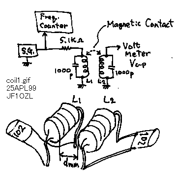
I bought a bag of junks in Akihabara town with 3 dallers. In this bag I could get the 1000 of micro inductors. I thought how I can use them. I had broken one of them. It was the solenoid coil winded around a chip of ferrite bobbin. I had an idea that to make double tuned circuit with it . And it may be used on the IF amplifier of the receiver. I arranged a pair of coils and capacitors , and by bending the leg of coils, I tuned the distance of them. I changed the frequency of the signal generator, and took the data of the output voltage of the second coil. I could know the following results from this experiment.
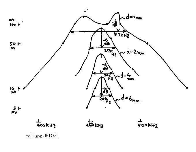
1. The narrower the distance of the coils, the bigger the second voltage becomes. It means the magnetic connection of each coils becomes stronger.
2. The more far the distance becomes, the shape factor becomes the better. But the better shape more than 20kHz with -6dB could not be achieved.
3. When the coils are arranged with too narrow distance from each other, the shape becomes like a doubly peaked mountain like Mt. Tsukuba seen from my town.
4. 4mm distance is the best point as a doubly tuned band pass filter in this case. I do not know how you call it in English, because I learned it in the Japanese text book. HIHI.
5. These coils can make a magnetic connection very easy, therefore I will not be able to use it unless a proper shield case on the IF filter of the receiver. But I could make experiment and enjoyed to know about the double tuned band pass filter very easy. Therefore I showed this data for you.
コイルの基礎実験:複同調の磁気結合係数とバンドパス特性に関して。
秋葉原で300円のジャンク袋を買ったところ、その中にマイクロインダクターと呼ばれる小さなコイルがたくさん、およそ1000個程度はいっていました。なにしろただみたいな物ですから、これで何かに使えないかと考えていました。一つ取り出して壊してみた所、中には、ソレノイドタイプのフェライトコアに細い線がいっぱい巻いてあり、これを樹脂でかためて有りました。ひとつのアイデアとして、このコイルを2個使って、磁気結合させてバンドパスフィルターが作れないか、実験してみる事にしました。下の図にような回路で、シグナルジェネレーターの電力をL1のコイルに印加して、そのすぐそばにL2のコイルを置いて、共振させて2次側の電圧を観察しました。周波数を振って、出力電力(V0センターツーピーク)で、測定しました。L1とL2は横に並べて配置し、リード線を曲げて、二つのコイルの間隔(dmm)を調節してデータを取ってみました。結果を下グラフに示します。この実験から下記の事がわかりました。
1.コイルの間隔は、近い方が2次側の電圧が大きくなる、これは1次側と2次側の磁気結合(M結合)が大きい事を意味する。
2.コイルの間隔を広げてゆくと、山の形がきれいなピークを示す様になり、選択性が改善される。しかし、ある程度以上離しても、それ以上はなしても形は変わらず、伝達が悪くなるだけである。すなわちピークからのー6dB下がった所の周波数幅が20kHzという同じ形であとは、これ以上はなしても山の高さが低くなるだけで、形は変わらない。
3.逆にぴったり付けると、「筑波山」の様に、ピークが二つできてしまう。
4.この場合は、間隔が4mm程度離れたところが、あまり出力電圧も下がらずに、選択性も良い結果をしめす。これが, いわゆる教科書で言うところの、「臨界結合」と呼ばれるポイントである。
5.結構二つのコイル同志が離れていても、電力が伝達される事から、この複同調回路自体を何らかのシールドで囲んでやらないと、中間周波のコイルなんかに使ったら、変な磁界を撒き散らすやら、迷結合するやらで、良い結果はえられそうにない。
といった事がわかりました。当初の目的である、複同調回路としての実用は難しそうですが、教科書に書いてある「臨界結合」の実験ができて、面白かったので、紹介しました。
coil1.gif

d=omm :コイルの間隔0mm
